rfid card reader d0 d1 meaning In this article, we are testing Third Party access controller with some of our card .
20pcs NFC Cards Rewritable NFC Tags NTAG 215 PVC Cards Blank Easy Convenient .
0 · wiegand rfid reader
1 · wiegand rfid arduino
2 · arduino rfid reader
How to use Quick Share: Find the file, photo, or content you want to share. Tap on the Share button. Select Quick Share. Your device will start .How to use Quick Share: Find the file, photo, or content you want to share. Tap on the Share button. Select Quick Share. Your device will start looking for devices with Quick Share activated .
D0 (green) and D1 (white) outputs are almost universally colored Wiegand readers. Back when Telaeris was developing our XPressProx mobile proximity reader to read HID Prox cards, we needed to demodulate the data directly from the RF signal (*).XPID is a rugged Android handheld badge verifier. It provides excellent performance barcod.
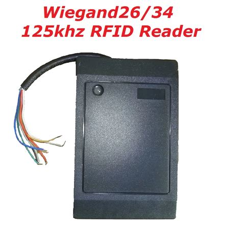
The Wiegand interface is for readers that could detect these cards output data .The Wiegand RFID reader is designed to read data from RFID cards or key fobs and convert it .The Wiegand interface is a de facto wiring standard which arose from the popularity of Wiegand effect card readers in the 1980s. It is commonly used to connect a card swipe mechanism to the rest of an access control system. The sensor in such a system is often a "Wiegand wire", based on the Wiegand effect, discovered by John R. Wiegand. A Wiegand-compatible reader is normally connected to a Wiegand-compatible security panel.
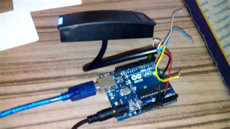
In this article, we are testing Third Party access controller with some of our card . I have connected two RFID readers with UNO board. Values that I am getting .
When “1” data is sent, DATA1 is pulled to low voltage and DATA0 stays at high .
Here's my complete code for checking a 26bit rfid card to grant or deny access .Resolution: A 26 bit Weigand Format is standard. It is one of the selections of the setup menu. . D0 (green) and D1 (white) outputs are almost universally colored Wiegand readers. Back when Telaeris was developing our XPressProx mobile proximity reader to read HID Prox cards, we needed to demodulate the data directly from the RF signal (*).
The Wiegand interface is for readers that could detect these cards output data over two signal lines called D0 (Data Zero) and D1 (Data One). This sequence of 1’s and 0’s is mapped to a binary number.
Toggle the switch of the selected Wiegand interface to READER mode. Connect the keypad reader's D0 wire to the D0 port of the Wiegand channel (Green - Data line 0). Connect the keypad reader's D1 wire to the D1 port of the Wiegand channel (White - Data line 1).The Wiegand RFID reader is designed to read data from RFID cards or key fobs and convert it into the Wiegand format for further processing. The reader consists of an antenna, a transceiver, and a Wiegand interface module.The Wiegand interface is a de facto wiring standard which arose from the popularity of Wiegand effect card readers in the 1980s. It is commonly used to connect a card swipe mechanism to the rest of an access control system. In this article, we are testing Third Party access controller with some of our card reader type. DHI-ASR1200 and DHI-ASR-1100. Below are the wiring diagram to connect the card reader using Wiegand Protocol:
I have connected two RFID readers with UNO board. Values that I am getting are like "255255223223223223255223223223-1-1-1-1". I want it to convert to card serial no.
When “1” data is sent, DATA1 is pulled to low voltage and DATA0 stays at high voltage. This signalling flow makes the data transmission process easier for the reader to convert to Wiegand protocol and transfer it to the controller for authentication. Here's my complete code for checking a 26bit rfid card to grant or deny access for a control access system.Resolution: A 26 bit Weigand Format is standard. It is one of the selections of the setup menu. The output data transmits from terminals marked Data 1, Data 2 and Ground. The first bit transmitted or received is even parity over the next 12 bits.
D0 (green) and D1 (white) outputs are almost universally colored Wiegand readers. Back when Telaeris was developing our XPressProx mobile proximity reader to read HID Prox cards, we needed to demodulate the data directly from the RF signal (*).
The Wiegand interface is for readers that could detect these cards output data over two signal lines called D0 (Data Zero) and D1 (Data One). This sequence of 1’s and 0’s is mapped to a binary number.
Toggle the switch of the selected Wiegand interface to READER mode. Connect the keypad reader's D0 wire to the D0 port of the Wiegand channel (Green - Data line 0). Connect the keypad reader's D1 wire to the D1 port of the Wiegand channel (White - Data line 1).The Wiegand RFID reader is designed to read data from RFID cards or key fobs and convert it into the Wiegand format for further processing. The reader consists of an antenna, a transceiver, and a Wiegand interface module.The Wiegand interface is a de facto wiring standard which arose from the popularity of Wiegand effect card readers in the 1980s. It is commonly used to connect a card swipe mechanism to the rest of an access control system.

In this article, we are testing Third Party access controller with some of our card reader type. DHI-ASR1200 and DHI-ASR-1100. Below are the wiring diagram to connect the card reader using Wiegand Protocol: I have connected two RFID readers with UNO board. Values that I am getting are like "255255223223223223255223223223-1-1-1-1". I want it to convert to card serial no. When “1” data is sent, DATA1 is pulled to low voltage and DATA0 stays at high voltage. This signalling flow makes the data transmission process easier for the reader to convert to Wiegand protocol and transfer it to the controller for authentication.
Here's my complete code for checking a 26bit rfid card to grant or deny access for a control access system.
wiegand rfid reader

ninty n215 nfc tags
programing nfc tag
Around the Promoted by Taboola. Get the latest 2024 NFL Playoff Picture seeds and scenarios. See the full NFL conference standings and wild card teams as if the season ended .
rfid card reader d0 d1 meaning|wiegand rfid arduino